Lesson 5: Putting it all Together
In this final lesson we connect the 3 subcircuits built in the last 3 lessons and add a few more components to create the analog step sequencer.
Zoom Recording of the Lecture
Link to the slides
Pre-reading
One new component we introduce this week is the diode. An LED, which we have used in almost every lesson, is a Light Emitting Diode. It is a certain type of diode that is similar to the generic diode we introduce in this lesson.
Recap
Over the past three lessons we built three circuits:
- Clock Signal
- This circuit used a single 555 to generate a square wave
- Sound Synthesis
- This circuit used two 555s to generate a tunable pulse wave that became sound
- Sequencer (Counter)
- This circuit used the 4017 to sequentially output 8 indenpendent signals
The goal of this lesson is to combine these three circuits, and add a few more components, to build the final analog step sequencer circuit which plays 8 tunable sounds at a configurable rate. This forms a basic customizable melody.
Additions
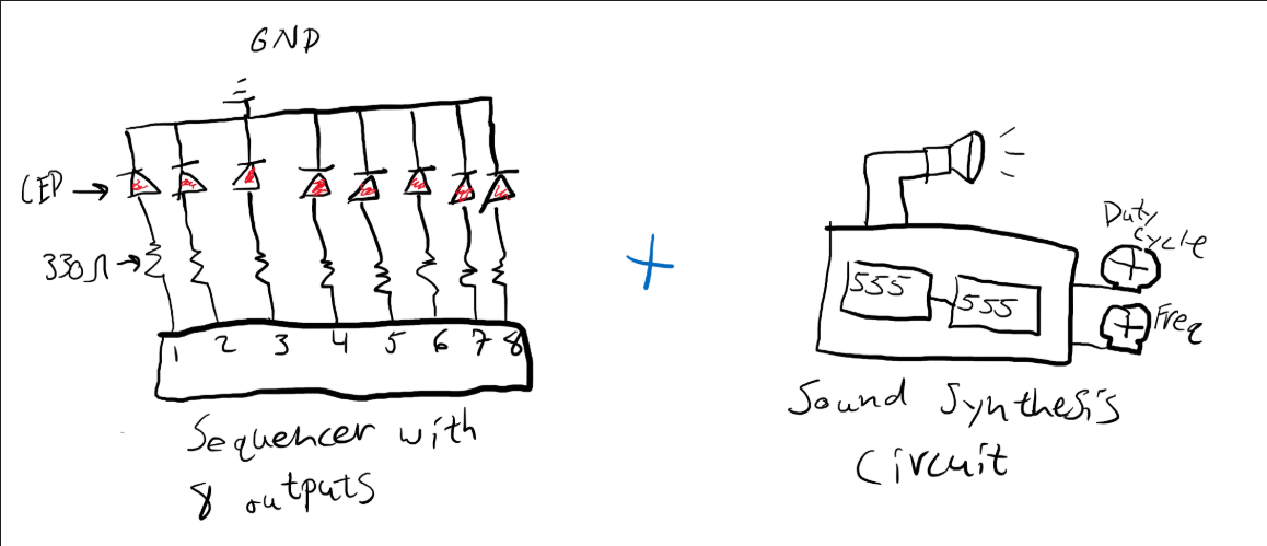
We already combined the clock circuit with the counter in order to generate a sequence that lit up 8 LEDs. Now we need to somehow combine this sequence with the sound synthesis circuit so that we can also play a tone at each step of the sequence. I drew a very simplified diagram showing these two subcircuits below.
If you remember, the sound synthesis circuit had two potentiometers. One was used to configure the frequency and the other was used to configure the pulse width. We want to be able to control the frequency at each step. To do this we will take the output of each step (where the LEDs are) and connect them to a potentiometer. Then we will funnel all these outputs to a single line which will be go to the sound synthesis circuit. This drawing below shows the general idea of what we want to do.
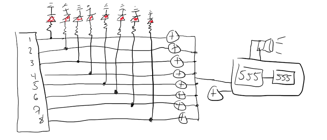
The main takeaway from this drawing is that now instead of having a single potentiometer control the frequency, we now have 8. So at each step of the counter, the frequency will be determined by the according potentiometer.
Issues
The diagram seems straightforward. At each step of the counter, one output goes high. This output goes through a given potentiometer (and lights up an LED) which determines the effective frequency of the sound at that step.
However, there are two issue with this setup.
- Look carefully at one output line in this circuit and look at where the current goes after the potentiometer. It goes to the sound synthesis circuit right. However, there are also 7 other paths it can go to which are the other output lines that are currently not active. The 4017 is able to sink current as well which means the current will also flow back into the 4017. The eact analysis of this effect is not trivial but we can see that this behavior is undesired, we want the current to go to the sound synthesis cirucit. To overcome this issue we will place diodes at each output line so that current can only exit this part of the circuit.
- The second issue with this circuit has to do with the 4017’s ability to supply current. If you look at the datasheet, there is graph showing the output current for different supply voltages. At around 9V, which is what we use, the chip can output just under 20 mA. This sounds like it should be enough but if you try to use this circuit with the default output current it doesn’t function properly. Most of the current will go to the LEDs and very little will go to the sound synthesis. This will cause the capacitor to charge much slower which creates sound at a very low frequency that is practically inaudible. TO overcome this we use BJTs to boost the output current at described in lesson 1.
Diodes
From the reading and from prior lessons we know that a diode only lets current flow in one direction. So why do we want to introduce this behavior into our circuit? With the LEDs it seemed like something arbitrary we had to remember when placing them into our circuit to make sure they would light up.
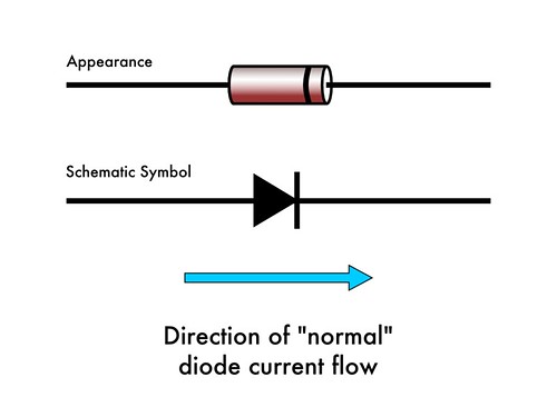
The reason is because sometimes we only want current to flow in one direction so that two parts of the circuit won’t interfere. Diodes can also be placed in the circuit in such a way to get some desired output signal. For example, a full-wave rectifier is a type of circuit that uses diodes to convert an AC to DC. As I mentioned above, we will use diodes to make sure the current doesn’t flow back into the 4017 chip.
BJTs
We looked at how we can use BJTs to boost current in lesson 1. We do the exact same thing in this circuit and place a BJT at each output line of the 4017. We could have also overcome this issue by simply using higher resistor values so that the LEDs would not require as much current. However, that would make them a bit dimmer and I thought that this would be a good way to show an application of BJTs.
Diodes and BJTs in our circuit
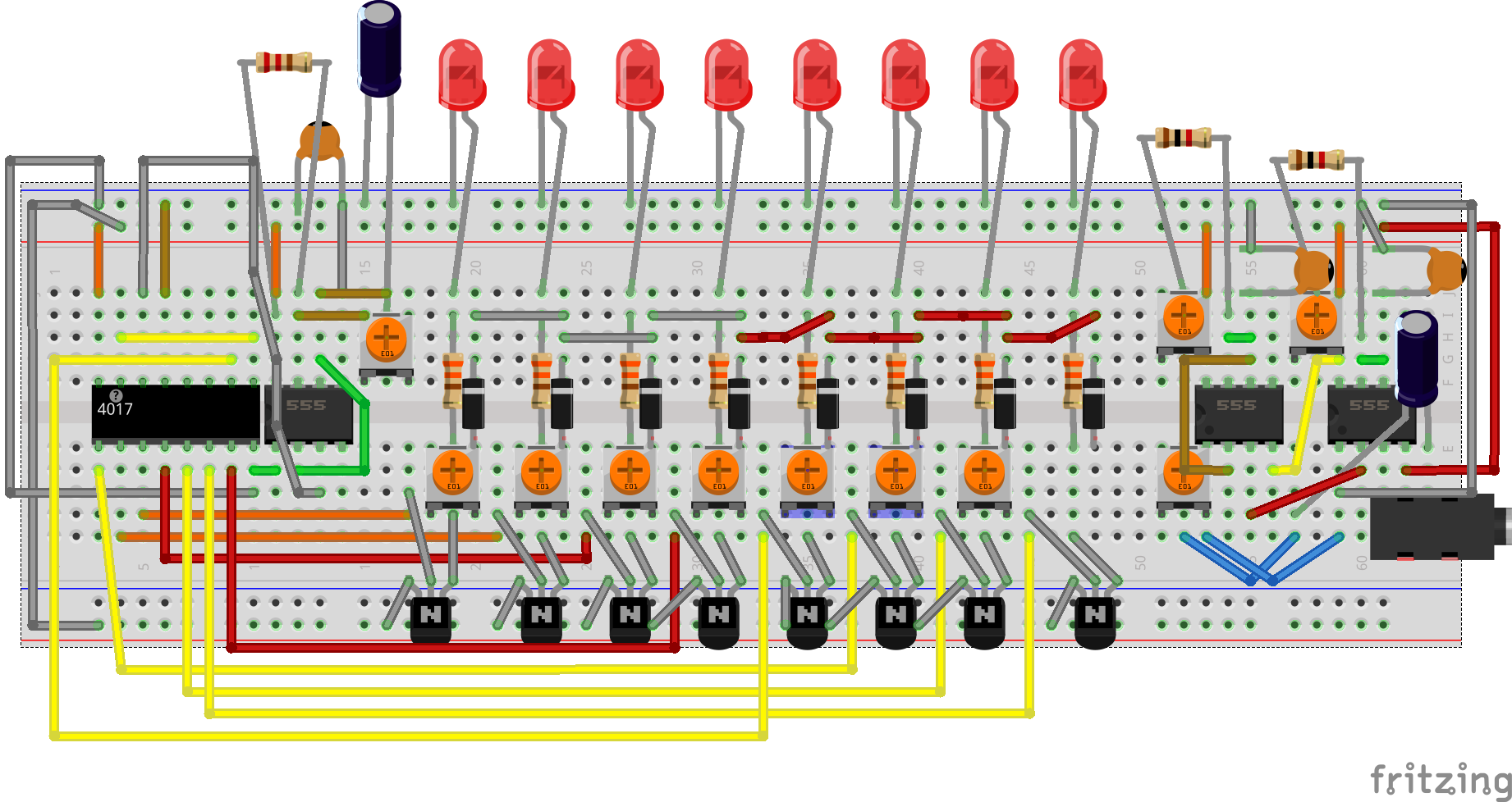
At the time of this lesson your circuit should look like the following:
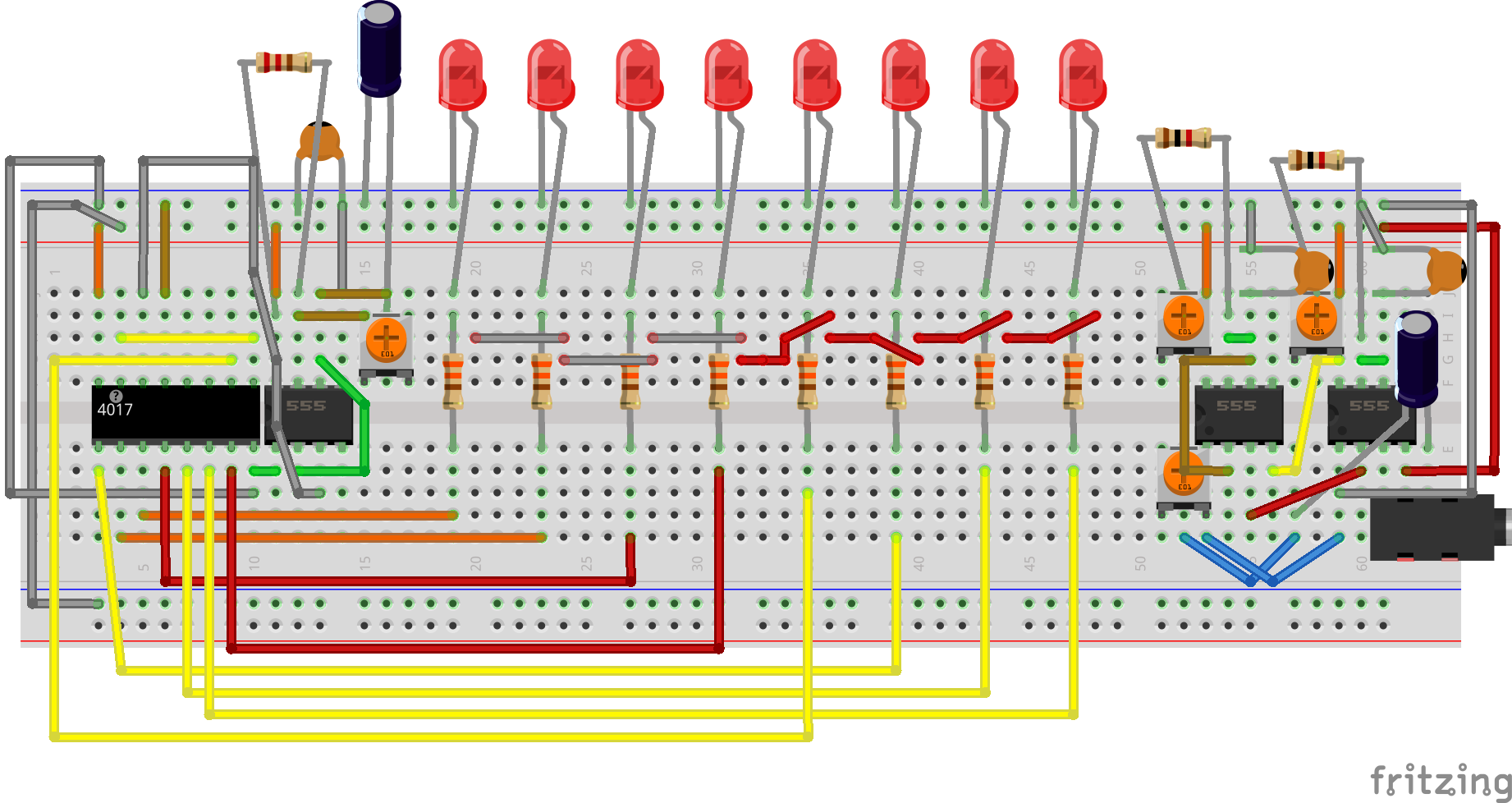
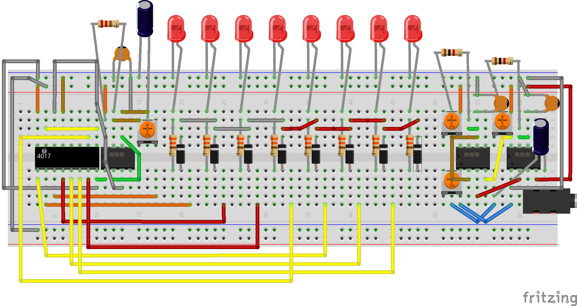
The first thing we want to do is move all the output lines two columns to the left and place the diodes adjacent to the resitors so that they are in the same column as the grey and red connectors underneath the resistors. The output lines should now be two columns two the left of the resitor that they were connected to. Our diodes look orange with a black line at the end. Make sure the black line is on the side of the LEDs. In this image the black line is represented by the white stripe.
 Next we add the potentiometers and BJTs. I show how to add a single potentiometer and BJT below. Note how the BJT and potentiometer are connected. The collector of the BJT (right leg if flat side is facing you) goes to the 9V rail. The base (center leg) of the BJT connects to the outputline. The Emmitter (left leg if flat side is facing you) goes to the the middle pin of the potentiometer. The left leg of the potentiometer is connected to nothing on the breadboard and the right leg goes to the diode. The result is that current flows from the output line to the base of the BJT. This current to the base gets amplified by the battery which is connected to the collector of the BJT. This current outputs at the emitter which goes from the middle to the right leg of the potentiometer and through the diode. All these diodes connect through the red and grey jumpers.
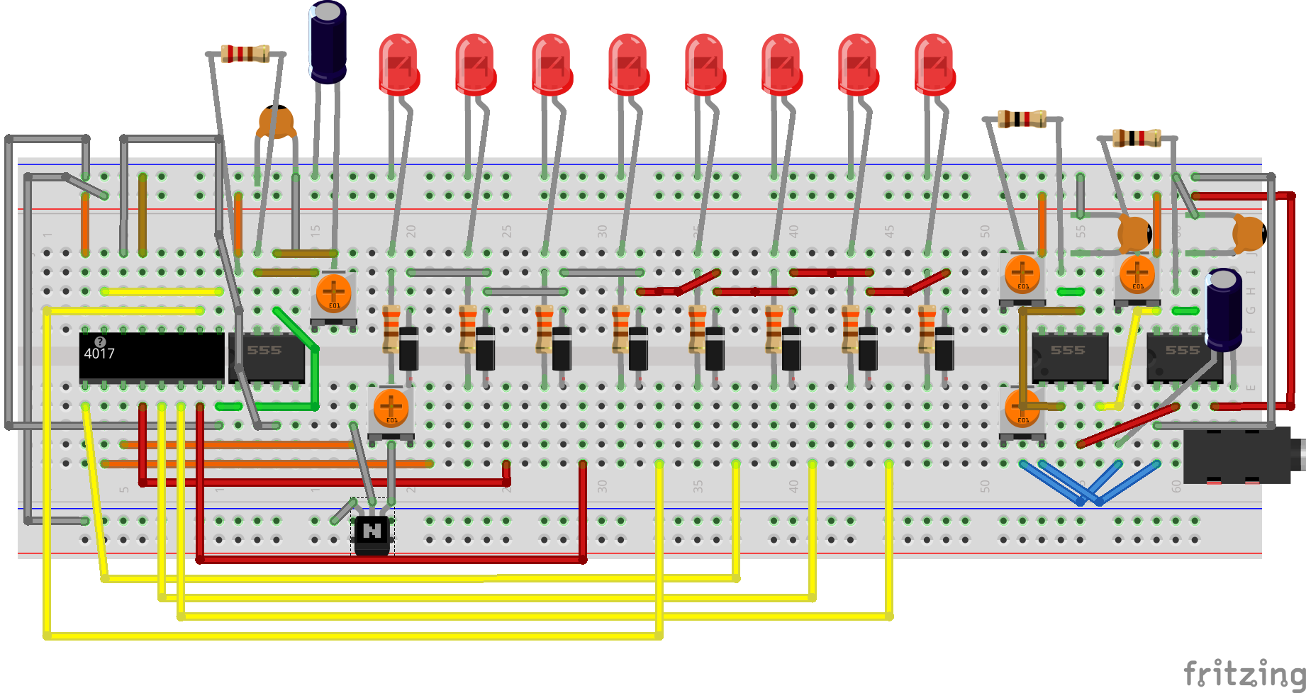
Now add this BJT-potentiometer connection to each output line as shown. You will notice that you are missing one potentiometer. That is because we used it for are isolated sound synthesis circuit. However, now we are connecting it so we can remove it from the isolated circuit and connect it to the eight output line.
The final step is to move that potentiometer to the 8th output line and connect the other end of the resistor to where all the diodes meet.
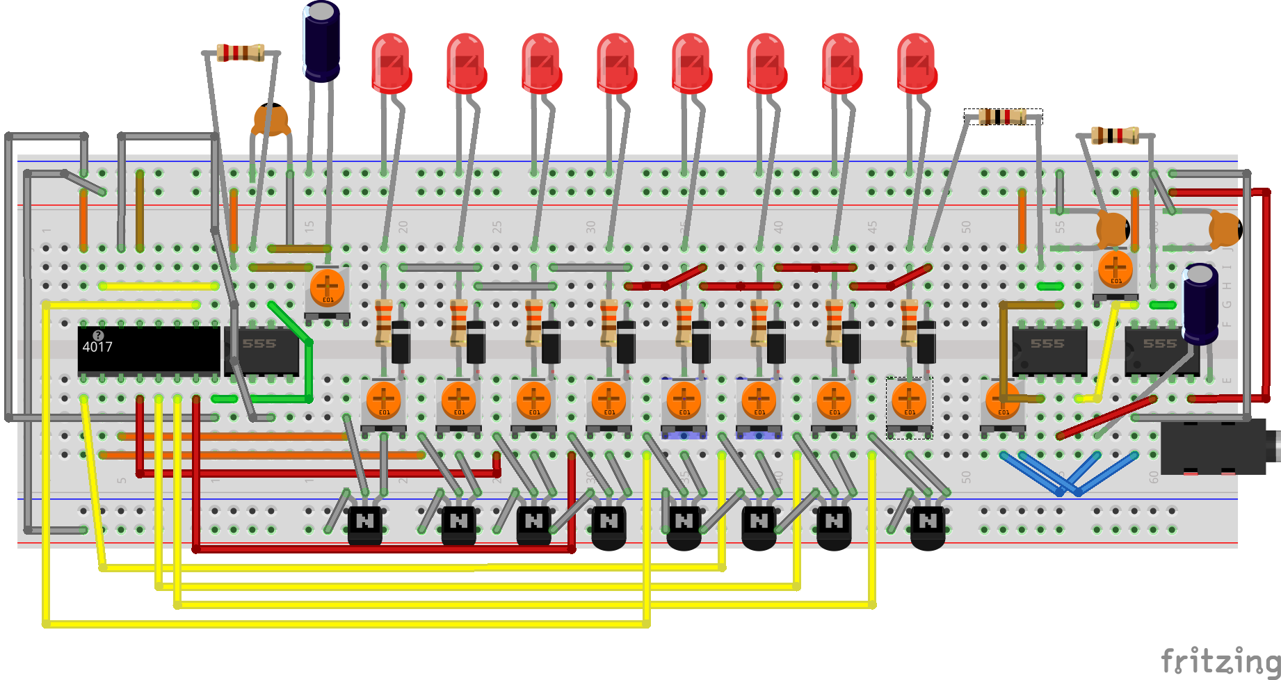
And that is it. That is the final circuit. Debugging this circuit can be a real struggle because there are so many connections on the breadboard. That is why I wanted to make sure that each subcircuit was working properly before connecting it up.
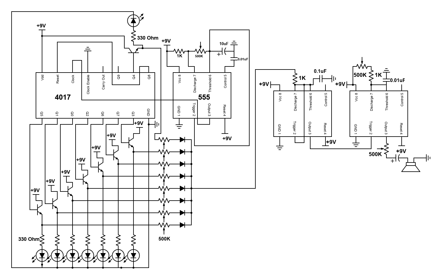
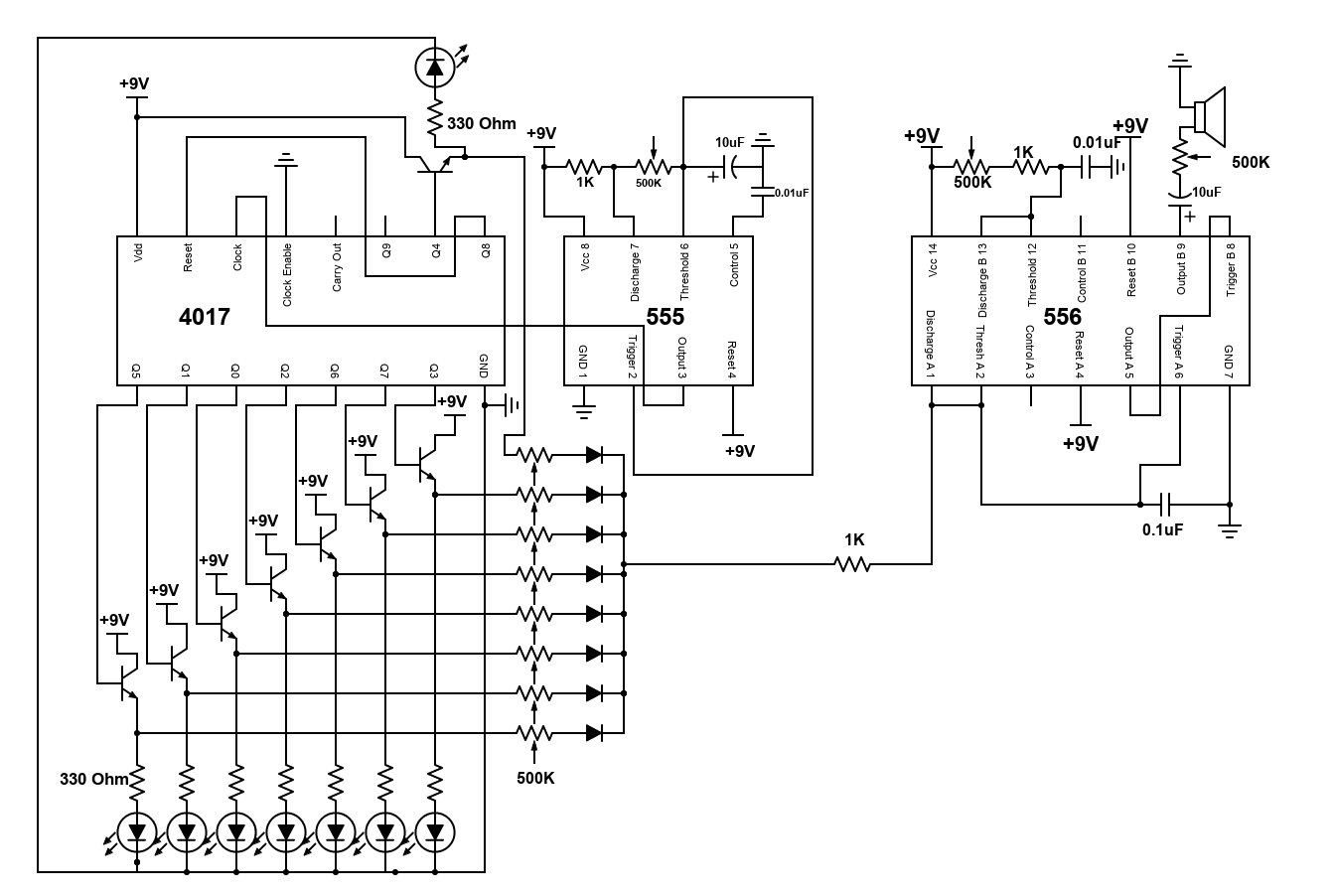
The final schematics which are easier to read are shown below.
I hope you enjoyed building this project and feel free to contact me if you are having trouble assembling the final circuit :)