Lesson 4: Creating a Sequence
In this lesson we introduce the last building block, the 4017 IC and utilize the clock circuit from lesson 2 to drive the sequence
See the recording for the note about the broken audio jack. If yours did not break then don’t worry about this
Zoom Recording of the Lecture
Link to the slides
Pre-reading
No new components are introduced this week but if you want to learn about how the 4017 counter chip works then first read this article on flip flops which are the building blocks of a counter.
The 4017 IC
The 4017 IC is a decade counter. This means that it counts sequentially from 1-10 and outputs a logic HIGH at a specified output pin (0-9). We will use this chip for the “sequencing” aspect of the project which ties together the circuits from the last two lessons.

This gif provides a nice visual of how the counter works. Note that this chip is driven by a clock (we will use the clock circuit we built from lesson 2!)
- As you can see, at each clock pulse, the next output (Q0-Q9) goes high
- This is what is meant by counting, the output pins go high sequentially
- Something that is a bit hard to see here is how the counter goes back to zero which is controlled by internal logic of the chip
- We are going to trigger the counter to go back to zero manually because we only need to count from 0-7 (8 times) because we have 8 outputs
Pinout
The 4017 has 16 pins which may seem like a lot but this chip is actually very straightforward to use.
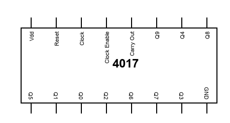
As we did with the 555 IC let’s distinguish the significant pins from the insignificant pins so that we can understand how the chip works.
Insignificant Pins
Again by insignificant, I mean pins that don’t require too much thinking
- Pin 16: Vdd. This is power so we just connect this pin to the +9V rail
- Pin 8: GND. This is ground so we just connect hthis pin to the GND rail
- Pin 13: Clock Enable. This pin controls whether the counter is “on”. We always want the counter to be on so we will connect it directly to GND (the pin is active LOW). If this pin is high the counter will ignore the clock and pause so that the current output will hold.
- Pins 11 and 12: Q9 and Carry out. As stated before we only want to count 8 times so we will ignore these pins and not hook them up to anything
Significant Pins
- Pins 1-7 and 10: Output pins. These are the counter outputs and will output sequentially from Q0 - Q7. Note that Qi is not connected to pin i so we need to make sure we are looking at the pin for which a given Qi is connected. For example, Q0, the first output is at pin 3.
- Pin 14: Clock. This pin drives the counter and will cause the next output to go high at each rising edge of the clock. Essentially, when are clock goes high, the next output goes high. We connect the output of our 555 clock circuit (pin3) to the clock pin of the 4017 (pin 14). If we speed up or slow down our clock using the potentiometer, the counter will count faster or slower as we will see. This will enable us to control the speed at which our sequence plays
- Pin 9 and 15: Q8 and reset. When the reset pin goes high, the counter goes back to its initial state which is Q0 goes high. We will connect the ninth output (Q8) to the reset so that once our counter reaches Q8 it will reset. So what will happen is our count goes 0 –> 1 –> 2 –> 3 –> 4 –> 5 –> 6 –> 7 –> 8 (trigger reset so pin 0 actually goes high) –> 1 …
That is all 16 pins. If you see a strange output (LEDs flickering or not counting correctly) the clock output may be noisy. Placing the 0.1uF capacitor on 555 pin 5 to ground should fix this. We originally used the 0.01uF capacitor for this but we had to switch it for the synthesizer circuit.
That is it for this lesson. I wanted to keep it short this week because the next lesson is the last lesson and we will be connecting this counter circuit to the sound synthesizer circuit (this part is a little tricky). It is important that both these circuits are functioning before we connect them because debugging the final circuit is very difficult, especially over zoom :).
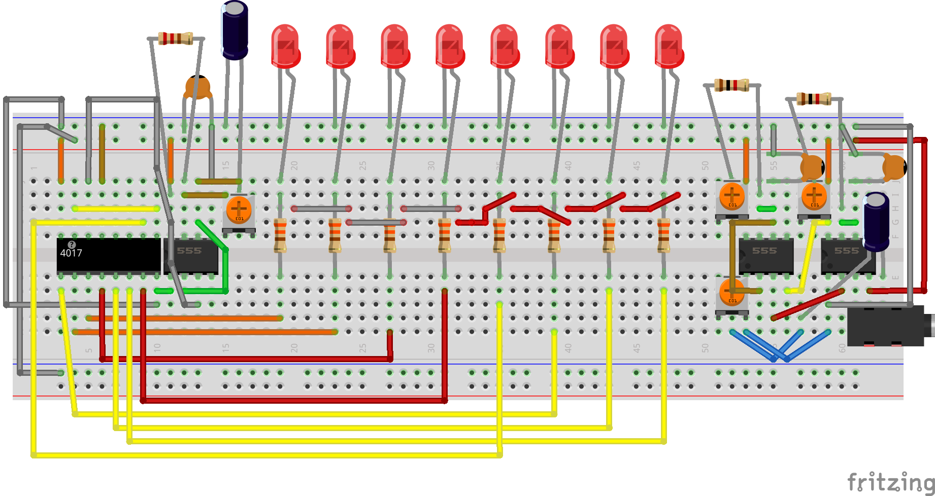
Circuit Diagram
This diagram is kind of messy so you may want to refer to the slides for a sequential assembly of the circuit