Lesson 3: Sound Synthesis
In this lesson we will use two 555 timers to build a sound synthesis circuit
I found a mistake in the parts for this circuit. I thought I was using two 0.1uF capacitors but was actually using a 0.01uF and a 0.1uF capacitor that just look very similar. The sound won’t sound so great with two 0.1uF capacitors so we will replace one with the 0.01uF capacitor from the previous lesson which was used to reduce noise.
Zoom Recording of the Lecture
Link to the slides
Pre-reading
No new components are introduced this week
- What is Sound
- This article talks a little bit about the physics of sound.
- How speakers work
- This webpage gives a brief explanation of how speakers work
- What is inside your earbuds
- This page talks about what is inside an earbud
The 556 IC
If you ordered the components on your own then you will have a chip called the 556 IC instead of two 555 ICs. This is just two 555 ICs packaged together into one chip. It was cheaper to buy many 555 ICs in bulk but one 556 IC for individual purchase. They work exactly the same just with a different pinout so I will discuss both.
Before we talk about the circuit, let’s talk about sound.
Making Sound
From the article in the pre-reading, we know that in order to create sound we need to vibrate an object. As the object vibrates, it causes the air around it to vibrate which creates a sound wave that we can hear. A couple questions?
- What object are we vibrating?
- The circuit we build cannot actually generate sound itself, but rather it generates an electric signal that gets transformed into sound using a speaker or earbuds.
- The object that vibrates is a flexible plastic “cone” inside the speaker or earphone (see the article for visuals)
- How do we generate those vibrations?
- If you remember from lesson 2, we created a square wave. This wave is an oscillating voltage which essentially results in oscillating current. When the current travels through a coil it essentially creates an electromagnet which interacts with a permanent magnet attatched to the cone.
- As the current oscillates, it flips the polarity of the electromagnet, which pushes and pulls the permanent magnet which oscillates the cone, creating sound. (Something to note is that the square wave we generated is always postive so this will only move the cone in one direction. We add a capacitor inline with the speaker to remove the DC offset)
- This pulse wave will create a buzzing sound. As we change the pulse width and frequency using potentiometers we can make cool and intersting tones.
Why Use Two 555 ICs and How Does that make sound?
Square Wave vs Pulse Wave
- If you recall from the previous lesson, the timing capacitor took the same amount of time to charge and discharge because both the charge and discharge paths were through the 500K potentiometer
- This created a square wave which has a *duty cycle of 50% meaning the time the wave was high and low was equal
- Also recall that as we rotated the potentiometer, the frquency of the square wave increase or decreases because the capacitor takes a shorter or longer amount of time based on the series resistance. However the relative High and Low times were still equal.
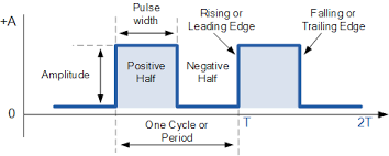
In this image we see a generic pulse wave. When the “negative half” and “postive half” are equal then we get the special case of the square wave. As we will see, when we change the width of these (in addition to the frequency) we will get different and interesting sounds.
In order to change these two values we need two 555 ICs
- One will control the frequency and the other will control the duty cycle
- We can attempt to do this with one 555 IC but we won’t be able to control these two characteristics seperately
Circuit Diagrams
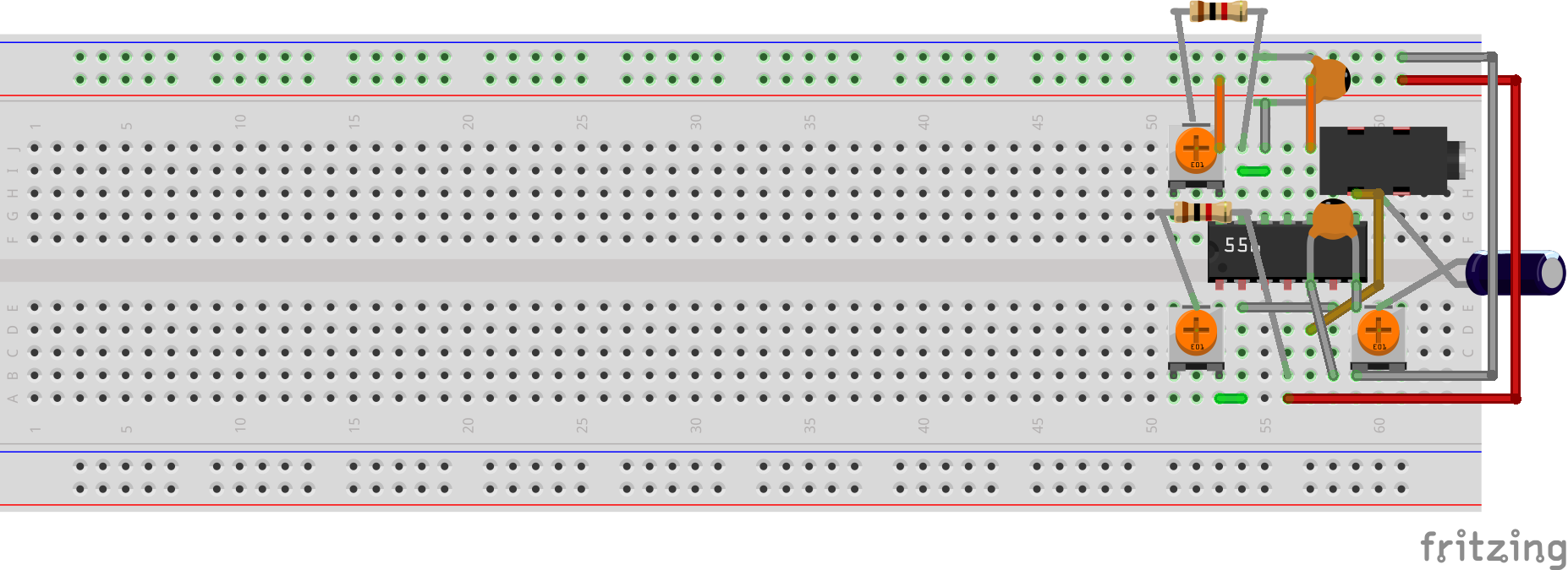
Below are the two circuit diagrams. If you ordered parts from me then refer to the diagram with two 555 chips. If you ordered the parts on your own then refer to the diagram with the long 556 chip
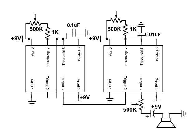
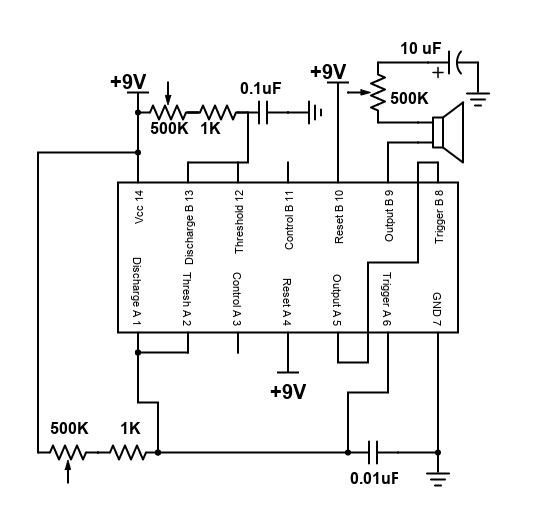
There is a slight mistake in the diagram for the 556. The capacitors should be swapped. However, I reccommend both configurations as an experiment to see which one creates better quallity sound
If you look at the circuit closely you will see that there isn’t anything new except the output to the speaker/earbuds
- Essentially we just build the same circuit as last lesson but cascade two of them in a row.
- However, note that the second circuit does not have feedback
Assembling this circuit should be straightforward given that a very similar circuit was assembled last lesson. The tricky part that is a bit subtle is understanding how connecting the these two chips together alters the waveform.
The left circuit (bottom circuit for 556)
- The 555 IC can be used in multiple modes and last lesson we explored two of them
- Monostable mode: this was the pulse circuit that generated a single pulse when the button was pressed and then did nothing until the button was pressed again
- Astable mode: this was the clock circuit that had feedback and kept triggering itself to generate the square wave
- The circuit on the left is in astable mode and is almost identical to the clock circuit from last time. The difference is that the 500K potentiometer is placed in a different spot because we don’t necessarily want a uniform square wave
- In this circuit the capacitor discharges very quickly so the low time is very short. As we adjust the potentiometer we adjust the pulse width of this circuit and effectively the duty cycle
The right circuit (The top circuit for 556)
- In the right circuit the 555 is being used in monostable mode because there is no feedback
- Also notice that the output of the left 555 goes to the trigger of the right 555
What is happening between these two circuits
To understand what is happening let’s look at a timeline
- At time t=0 the left capacitor is discharged meaning that pin 2 is low
- Pin 2 low triggers pin 7 to “turn off” so that the capacitor starts charging through the potentiometer. Also the output at 3 goes high
- The output at 3 now goes into the input at 2. This 555 behaves in a similar manner, meaning that when pin 2 goes low pin 7 turns off and the capacitor starts charging and the output goes high
- So currently the output on 3 for the left 555 is high meaning that pin 2 on the second 555 is also high which does not trigger anything
- At some later time t1 the left capacitor charges to the threshold which causes pin 7 to turn on, the capacitor to discharge, and the output at 3 to go low
- This low output at 3 triggers the right 555 timer to start
- The right 555 timer now starts charging and the output at its pin 3 goes high
- Since this 555 has no feedback, once the capacitor reaches the threshold pin 3 will go low until the left 555 timer triggers the whole process again
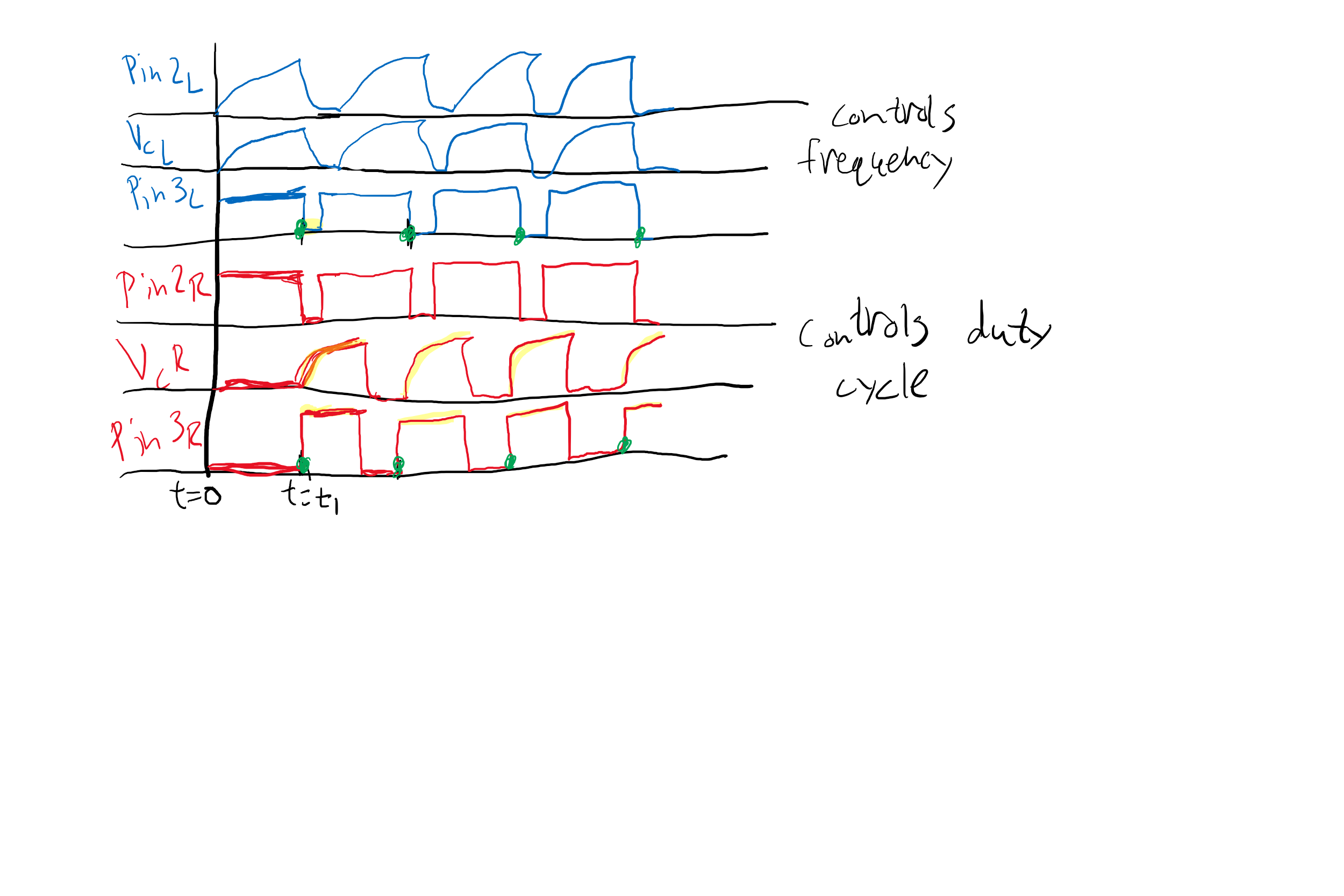
This timing diagram should give you an idea of how each 555 controls the output.
- The left one (blue) controls the frequency because it only allows the right 555 to trigger whenever it goes high. Otherwise the right 555 will do nothing
- The right one (red) controls the duty cycle or pulsewidth of the output signal because once it is triggered it will cause the output to go high until the capacitor is charges to the threshold voltage
Choosing different capacitor values will result in different output. I found that these values work best and give a nice output. See what happens when you switch the capacitors.
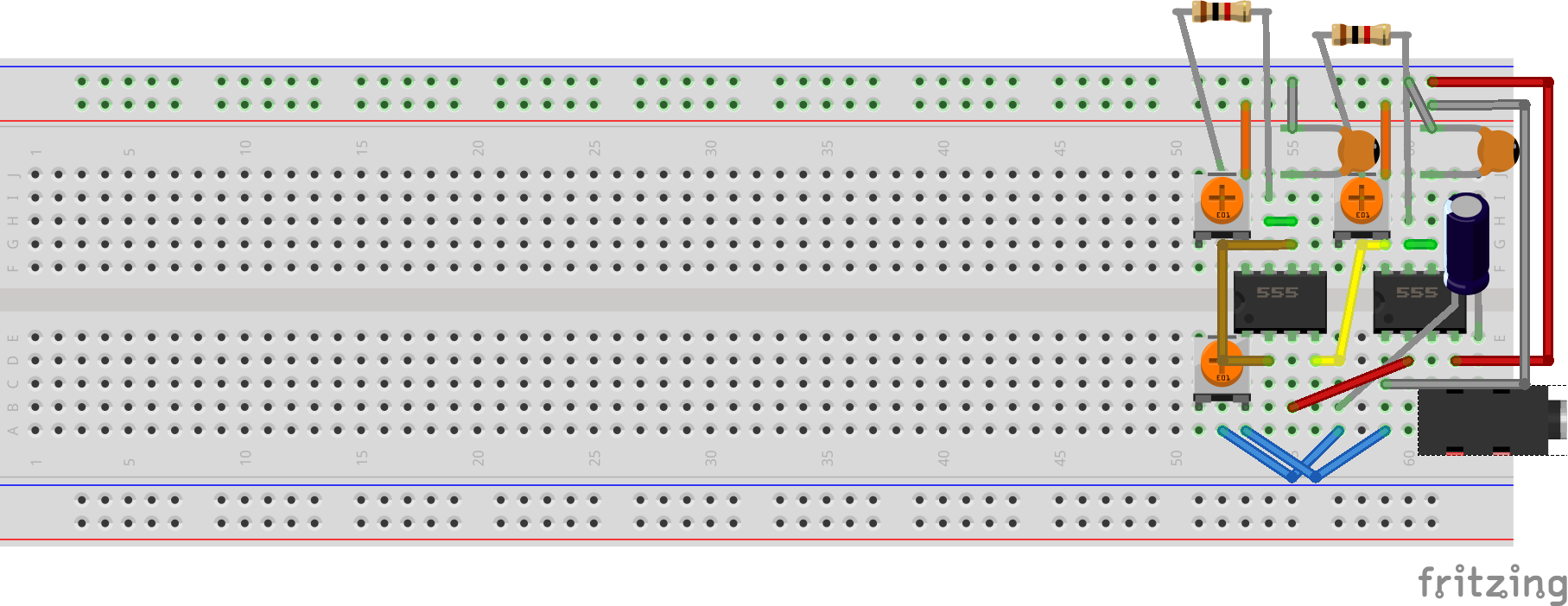
The following is the diagram of the breadboard circuit. Be very careful when placing the audio jack because the legs are fragile. Once you place it into the board, I don’t reccomend taking it out. In fact, this will be the final location of the this circuit for the final project so we won’t need to move any of these components.
These diagrams are quite messy as it is hard to show where all the components are without overlapping. Note the color of the wires here, I chose them specifically so that you won’t have to figure out which lengths to use.
There is an error with one of the connections in this circuit. I have the long red wire connected to the ground rail(blue) and the long gray wire connected to the power rail(red). This should be flipped so that red goes to red and grey goes to blue as shown in the second diagram