Lesson 2: Introducing the 555 IC
In this lesson we explore the 555 IC (Integrated circuit).
Zoom Recording of the Lecture
I figured out why the demo for circuit example 1 did not work. I needed to connect a pullup resistor so that pin2 would default to high
Link to the slides
Pre-reading
- What is an integrated circuit
- If you have never heard of an integrated circuit, you may want to look at this article
What is the 555 IC
The 555 IC is the most important component of our project, so important that we use three of them. It is essentially a “timer chip” that we will use in a couple of different ways.
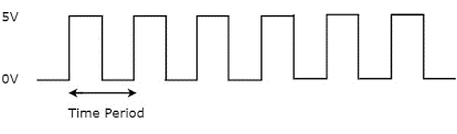
- The first way we will use this chip is to generate a clock signal shown below. Each time the clock signal goes high, it will trigger the next tone of the melody to play; its frequency dictates the speed of the melody.
- The second way we will use the chip is to create tones. This requires two 555 ICs and will be covered next lesson.
How the 555 Works
We can view the 555 IC and ICs in general as an abstractional unit or black box. The internal workings can be very complex and for the most part all we need to understand is how to use the pins.
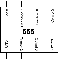
Pinout
This image to the left is the pinout diagram of the 555 chip which tells us the purpose of each pin. Even though there are 8 pins, only 4 of them have significant meaning.
Insignficant Pins
Pin 1 is ground, Pin 8 is power supply. We connect these to ground and power rails on the breadboard. Pin 4 we don’t use and can disable by connecting it to our power rail. Pin 5 we also don’t use and can be disabled by connecting it to ground through a 0.01uF capcitor which reduces output noise.
Significant Pins
The remaining four pins are used to control and tune the 555 to behave how we want. To understand how these pins and the 555 work it is best to look at an example.
Using the 555 to generate a pulse
One of the simplest uses of the 555 is to create a single pulse (a single square wave). This is referred to as monostable mode and is a good way to understand how the 555 works. Don’t worry about building this circuit, it is just an example.
The Circuit for using the 555 in monostable mode
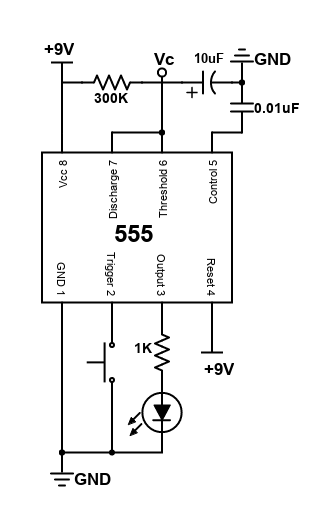
as mentioned above, there needs to be a pull up resistor connected to pin 2 so that when the button is not pressed, pin 2 will default to high. Also the 1K should be 330Ohm
In this diagram we can see that pins 1, 8, 4, and 5 are connected as described above. Now let’s take a look at pins 2, 3, 6, and 7. Something important to note is that the 555 is not a plug and play, it requires some external components to work.
The reason for the external components is flexibility. We want to control the pulse width and frequency of the output. To control these characteristics, an external RC (resistor capacitor) circuit is used.
Based on the values of the resistors and capacitor in the circuit, the capacitor will take a certain amount of time to charge and discharge which directly influences the pulse width and frequency at the output.
Pin 2 is the trigger pin and is used to “start” the charging of the capacitor. It is active low which means it activates when it has a voltage less than 1/3 the source voltage. Here we use a button to toggle the state of pin 2.
Pin 3 is the output pin and is where we get the pulse from. We conenct pin 3 to an LED through a resistor so that we can visualize the output.
Pin 6 is the threshold pin and monitors the capacitor voltage. When the voltage at this pin is greater than 2/3 the supply voltage, it causes the output at pin 3 to go low.
Pin 7 is the discharge pin and is used to discharge the capacitor.
A quick note about pin 4 and 5. Pin 4 is the reset. If we pull this pin low it will cause the timer to reset. It won’t start until pin 2 triggers it again by going low. Pin 5 is the control voltage and can be used to alter the threshold voltage.
Quick Explanation on RC Circuits
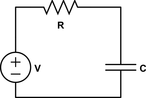
A capacitor is a circuit element that stores charge. However, the current-voltage relationship for a capacitor does not follow Ohm’s law and is time-dependent
Connecting a capacitor accross a voltage source will draw a lot of current so we use a resistor to limit the current. The value of the resistor (and capacitor) affect the time it takes for the capacitor to charge/discharge.
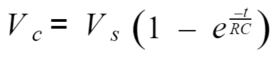
If we have a large resistor, then little current will flow so the capacitor will take longer to charge/discharge. Likewise, a large capacitor can store a lot of charge so it will take longer for it to charge/dischage. This resistance-capacitance value is called the time constant and is seen in the equation below as RC
Voltage of a Capacitor in a Charging RC Circuit (Vs = source voltage)
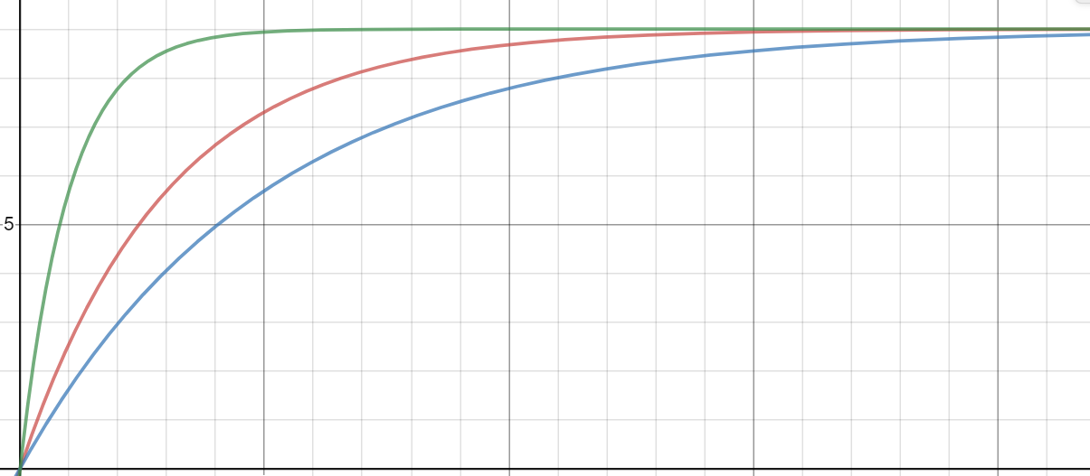
These three curves show the capacitor voltage vs time for an RC circuit when the capacitor is charging up.
The green curve has the smallest time constant and charges up to the source voltage (+9v here) the quickest and the blue curve has the largest time constant and charges up the slowest.
By toggling the resistor and capacitor values we change time it takes for the capacitor to charge. Typically the capacitor stays constant while the resistor value changes. We will use a potentiometer (essentially a variable resistor) to change the time constant.
Note: RC is the time is takes for the capacitor to charge to ~63% of the source voltage starting from 0, or to discharge to ~37% of the source voltage starting from Vs. In our circuit, we want to know how long it takes for the capacitor to charge to 2/3 Vs (66%) or discharge to 1/3 Vs (33%). So if we replace Vc with 2/3 Vs in the equation for Vc and solve for t, that will tell us how long until the capacitor voltage reaches 2/3 Vs. The answer ends up being ~1.1RC.
This article may help if this is still confusing.
Coming Back to the 555 “Pulse Circuit”
Now that we understand the basics of an RC circuit, we can see how it enables us to control the behavior of the 555 chip.
- At time t = 0, the 10uF capacitor is discharged, Vc = 0. We press down the button to connect pin 2 to ground.
- When Pin 2 goes low, it causes pin 7 to “turn off” so that the 10uF capacitor no longer discharges and now starts charging up through the 300K resistor. Also, the output at pin 3 goes high, slightly less than the source voltage.
- At time t = t1, the capacitor has charged up to 2/3 of the source voltage. 9V * 2/3 = 6V. When this happens, the output at pin 3 goes low again and pin 7 “turns on” which enables the capacitor to discharge.
Note that the charge up time of the capacitor correlates to the pulse width and the discharge time correlates to the frequency. In the case of a single pulse the frequency has no meaning but it will when we send multiple pulses. Also, in this circuit there is no resistor between the capacitor and pin 7 so it will discharge very quickly.
Using the 555 to generate a Clock Signal
Now we are going to modify our circuit slightly so that instead of sending a single pulse, we send it repeatedly and create a clock signal.
The Circuit for Using the 555 as a Clock
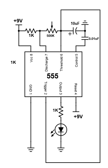
The bottom 1K resistor should be 330 Ohm
The goal of this circuit is to repeatedly send pulses. To do that we must have some sort of feedback, meaning that one pulse cycle is complete, it needs to trigger the next pulse to send.
Before, we did that by pressing the button. Now, we remove the button and connect pin 2 directly to pin 6. Remember that pin 2 is the trigger pin and “starts” the timer when it goes low and causes the output to go high. Also, pin 6 is the threshold and causes the output to go low when it reaches 2/3 the source voltage.
When we connect pin 2 to pin 6 we create feedback in this way:
- At time t=0 the capacitor is discharged, Vc=0. Since the voltage at pin 2 is now equal to Vc, it starts the timer because Vc=0.
- Now time t = t1 the capacitor charges up and reaches 2/3 the threshold. This makes the output go low and turns on pin 7 so that the capacitor begins to discharge.
- Now at some later time t = t2 the capacitor discharges to 1/3 the source voltage which causes pin 2 to trigger once again. This cycle repeats over and over again.
Another change made to this circuit is the 500K potentiometer. This variable resistor can be used to toggle the clock frequency. In this circuit the pulsewidth changes with frequency but the duty cycle does not because the charge and discharge times for the capacitor are very close (1K resistor). In the next lesson we will see how we can change the pulsewidth and frequency of the output to synthesize sound.
The output of this circuit will be a square wave which we can visualize through the LED. Whenever the pulse is high (when the capacitor is charging), the LED will turn on. When the pulse is low (the capacitor is discharging), the LED will be off.
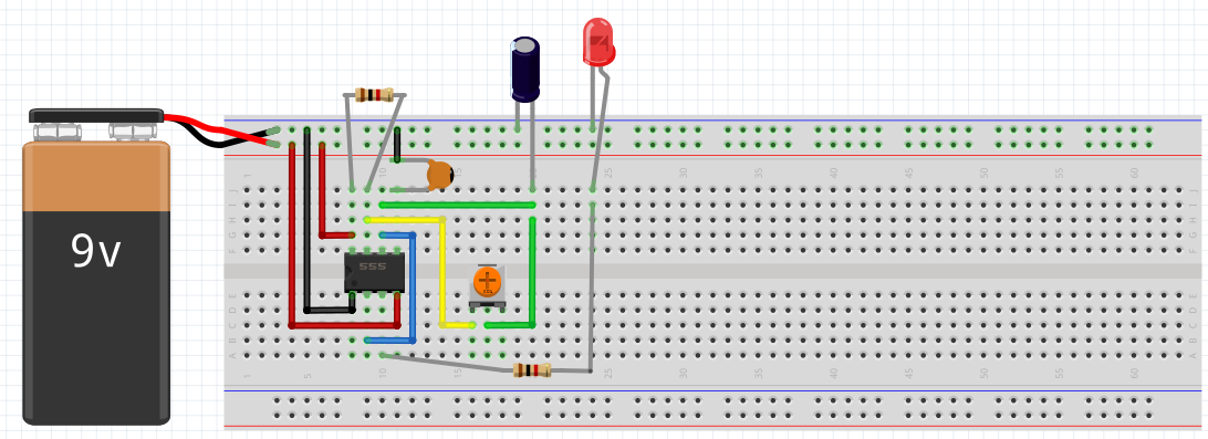
Clock Signal Circuit on a Breadboard
Taking a circuit schematic and assembling it on a breadboard can be tricky. This schematic shows one configuration of the components on the breadboard and can be used as a reference.