Class 4: H-Bridge
Now that we have a high current output from the amplifiers, we need high voltage. A transformer is used for just this. A transformer can convert voltage from high to low or low to high. The ratio of the input and output voltages is equal to the ratio of the number of turns of coil on the two coils of the transformer. A transformer is essentially just two inductors, which are essentially just coils of wire. So we have a transformer with ~10000 turns. We wrap a wire ~5 times for the secondary coil which gives us a turn ratio of the two coils of 2000. With a Vcc of 10v, we will get a ~20000V output. Inductors only have a voltage when the current is changing. In other words, it will only work when driven by an AC signal. The H-Bridge is used to convert our DC output from the amplifiers to AC. The basic circuit looks like this:
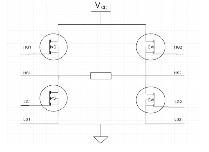
The three-terminal devices in the circles are MOSFETs (transistors). The top terminal is called the Drain the center terminal is called the Gate and the bottom terminal is called the Source. For our case, it is used like a switch. When the voltage between the gate and source surpasses a threshold voltage dependent on the MOSFET, it will allow current to flow between the Drain and Source. In other words, applying a voltage at the center terminal shorts the other two terminals together and it behaves like a wire. When there is not a voltage at the center terminal, the MOSFET behaves like an open circuit.
The rectangle in the center of the image above is where our transformer will be. Based on the inputs, two diagonal MOSFETs will be closed at a time. When the top left and bottom left
MOSFETs are closed, current flows from Vcc, through the left side of the transformer, out the right, and to ground. In the opposite scenario when the top right and bottom left MOSFETs are closed, current flows from Vcc, through the right side of the transformer, out the left, and to ground. This essentially provides negative voltage. At high frequency, you can see how the voltage across the transformer alternates from positive to negative, like an AC signal. The labelled HGX, HSX, LGX, LSX are from the amplifier circuit, where they are also labelled.
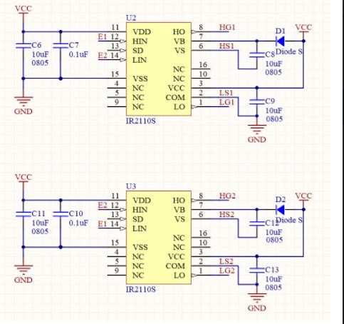
Now there are a few more components we use in the real circuit. Here are the schematics:
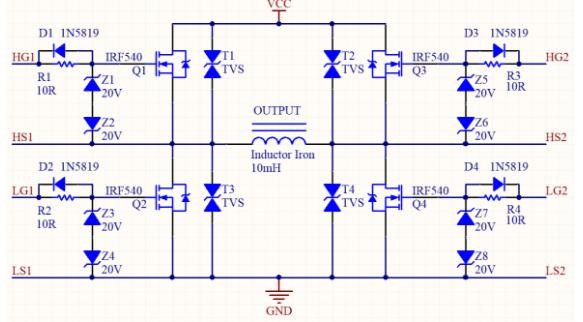
ZX are zener diodes. This will only allow current in one direction, provided the voltage does not exceed its maximum (20V in this schematic). These diodes can recover when the voltage is brought back down though, and work like normal. Normally Z1 will block current from flowing from gate to source of MOSFET 1. Given a high voltage on the gate, Z1 will break down and Z2 will allow current to flow to the source. The opposite will happen with Z2 and Z1 given a high negative voltage. These diodes will protect our MOSFETs in case of a voltage spike.
The TVS diodes perform the same function as Z1/Z2 but in a single component. We choose the two zener diodes instead because they are cheaper, but TVS are better for high power. These protect the MOSFETs from spikes on the drain. Our voltage supplies are stable, so we will omit these diodes.
Lastly are the resistor diode combinations. The resistor is used to limit the current to the gate. However, when the the diodes turn off, they need to turn off fast. If two MOSFETs on one side of the bridge are turned on simultaneously, Vcc will be shorted to gnd. So we allow the current to bypass the resistor when turning off by including diodes DX.