Class 1
Overview
We hear sound by our ears picking up vibrations in the air. As air heats up, it expands and as it cools, it condenses. The plasma speaker works by using a changing generation of heat to modify the vibrations.
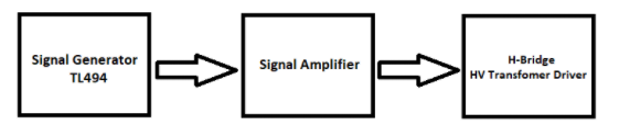
To build the speaker, we need to drive a flyback transformer with a music signal. In other words, our transformer needs to receive power relative to the music signal. We need three parts to accomplish this: a signal generator to convert the music signal into a usable format, a signal amplifier to generate enough power to drive the transformer, and the flyback transformer to deliver the music output.
Preface
Some important background information to know:
Potential
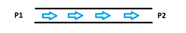
Consider a pipe which transfers water. As you may know, water flows from higher pressure to lower pressure. If point P1 is at a higher pressure than P2, water will be “pushed” from P1 to P2. Potential can be seen as the pressure at a given point.
Voltage
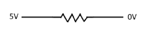
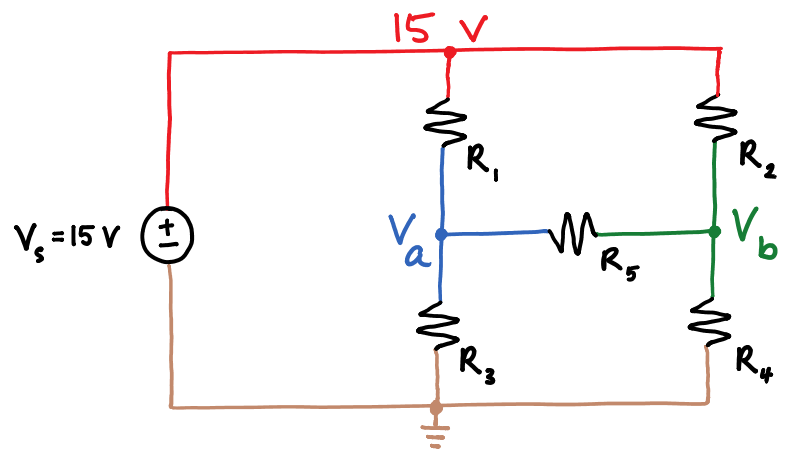
The difference in potential between two points is known as voltage. Consider the diagram above. There is a voltage drop of 5v across the resistor.
Current
Just like water flowing from high pressure to low pressure in the previous diagram, current flows from high potential to low potential.
Power
Imagine a water gun: if you have a lot of water in the gun, but not a lot of pressure, the beam of water is weak. If you have a lot of pressure in the gun, but not a lot of water, the beam is still weak. However, if you have a high amount of pressure and a lot of water, the beam is strong. The same applies in the electrical sense. Power is the multiplication of voltage and current.
Node Voltage
In a schematic diagram, branches that are connected together with no interrupting components are at the same voltage.
Signal Generator
What is it’s purpose in the circuit?
The TL494 signal generator encodes the input music signal into a PWM (Pulse Width Modulated) signal so that the circuit can be controlled using the input music signal.
PWM
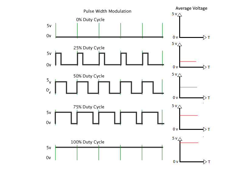
Pulse Width Modulation is the use digital square wave (a signal being switched on and off) to achieve analog results. The percentage of the time the signal is on is known as the duty cycle.
With a duty cycle of 100%, the signal is always on, and the average voltage is equal to the high level voltage (assuming a low level voltage of 0v). Likewise, with a duty cycle of 0%, the signal is always off, and the average voltage is equal to the low level voltage. With a duty cycle of 50%, the signal is on half of the time and off for the other half. The average voltage is half of the high level voltage.
The average voltage, and thus the average power drawn from the load at high enough frequency, will be high level voltage multiplied by
the duty cycle with a constant duty cycle. So with a 5V high level voltage and a constant duty cycle of 50%, the average voltage seen is
2.5V.
How do we operate the TL494?
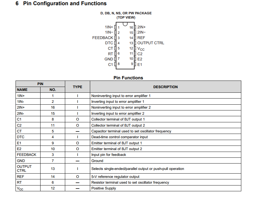
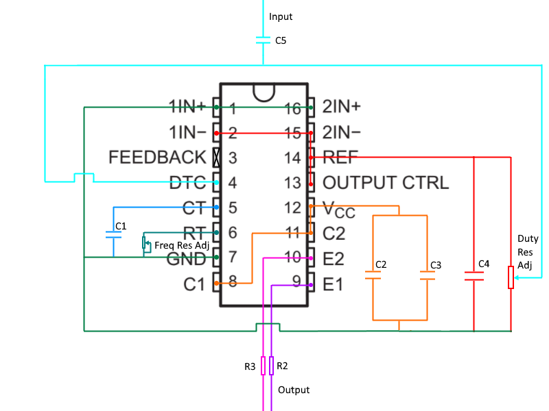
Above is the pinout of the TL494. To make sure the chip is oriented the right way, match the notch at the top of the drawing with the notch on the chip.
How do we include it in the circuit?
*Please note: The pin numbers are rearranged for clarity of the functionality
Chosen component values
C2 capacitor: 0.1 uF C3 capacitor: 10 uF C4 capacitor: 100 pF C2, C3, and C4 are filtering capacitors. These help smooth the supply voltages. If the supply voltage were to suddenly drop, the charged capacitors can supply voltage for that sudden moment.
CT capacitor: 1 nF
RT potentiometer: Adjusted to 40 kΩ
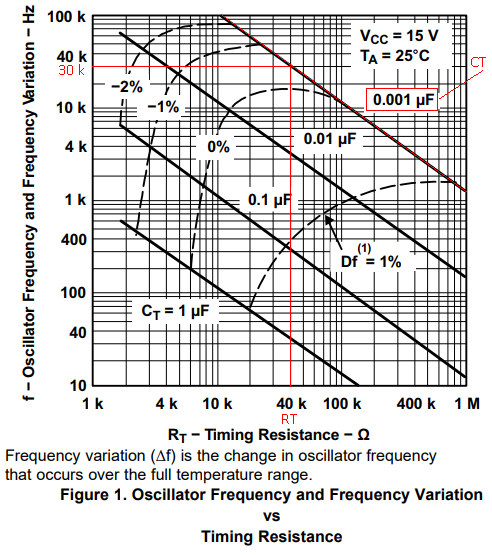
CT and RT used to set the frequency. A frequency of 30kHz is chosen because the human ear can hear signals up to ~20 kHz, and we don’t
want to hear noise produced by the circuit, only the music signal. These values were chosen in accordance to the graph on the datasheet
below. The diagonal lines represent the values of the CT capacitor, the x-axis represents the resistance values of RT, and the y-axis
represents the resulting frequencies. 30 kHz frequency intersects at 0.001 uF (or 1 nF) and 40 kΩ.
DTC potentiometer: Set to ~80 kΩ
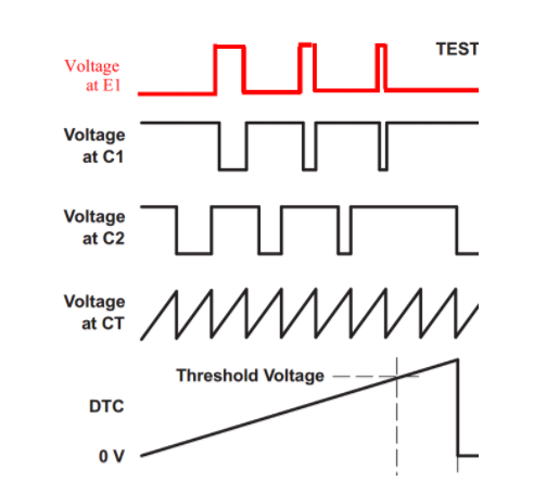
The DTC potentiometer serves as a voltage divider which will output a voltage VDTC0= 1V. This provides a base voltage for the music
signal to operate on. From the datasheet we examine DTC in relation to E1, our chosen output. We can conclude that increasing the DTC
voltage will decrease the duty cycle of E1, which means less power output.
Ideally, we would like the duty cycle of the output to change based on the voltage of the input music. The voltage of the music, Vmusic, added to the output voltage of the voltage divider VDTC0, should be our input voltage to the DTC pin. Thus, we want the following relationship: VDTC= VDTC0+Vmusic
This is not possible because MIDI and VDTC0share a node, and thus must be at the same voltage. However, consider the effect of having capacitor C5. If the capacitor is charged, adding Vmusicwill briefly make one side of the capacitor at a higher potential than the other. The result of this fulfils the relationship of VDTC= VDTC0+Vmusic
R2, R3: Between 0 and 10 Ω
Having some resistance on the line helps protect the circuit, but we keep the resistance small enough not to affect our signal.
INx+ and INx- (where x is 1 or 2)
INx+ and INx- are part of the op-amp inside the chip, which also changes the PWM. The lower the voltage difference of VINx+-VINx-, the lower A(VINx+-VINx-), and hence the larger the duty cycle. We don’t want this to affect our PWM so we connect VINx+ to 0V and VINx- to VREF (5V) so that VINx+-VINx-is negative. There cannot be a negative voltage amplification, so A(VINx+-VINx-) will be 0V, it will not affect our PWM output.
Cx and Ex (where x is 1 or 2)
Cx and Ex are the output terminals. Cx is the collector of the internal transistor and Ex is the emitter of the internal transistor. Ex is the inverse of Cx. We choose Ex for the non-inverted signal.
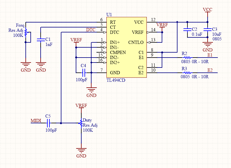
Wiring diagram
Below is an example of how the signal generator can be wired. Note the use of common nodes.