Class 5
This class discusses the base and final assembly.
You should now have the following items:
- 1x PCB mainboard
- 4x 12mm tact switch
- 4x tact switch cap
- 1x 6mm tact switch
- 16x 180Ω 1206 resistor
- 15x 10kΩ 1206 resistor
- 3x SN74HC595D (Shift register)
- 4x AO3400 (MOSFET)
- 1x SN74LVC1G32DCKR (OR gate)
Soldering the SMD resistors
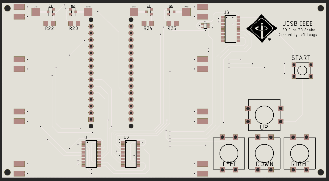
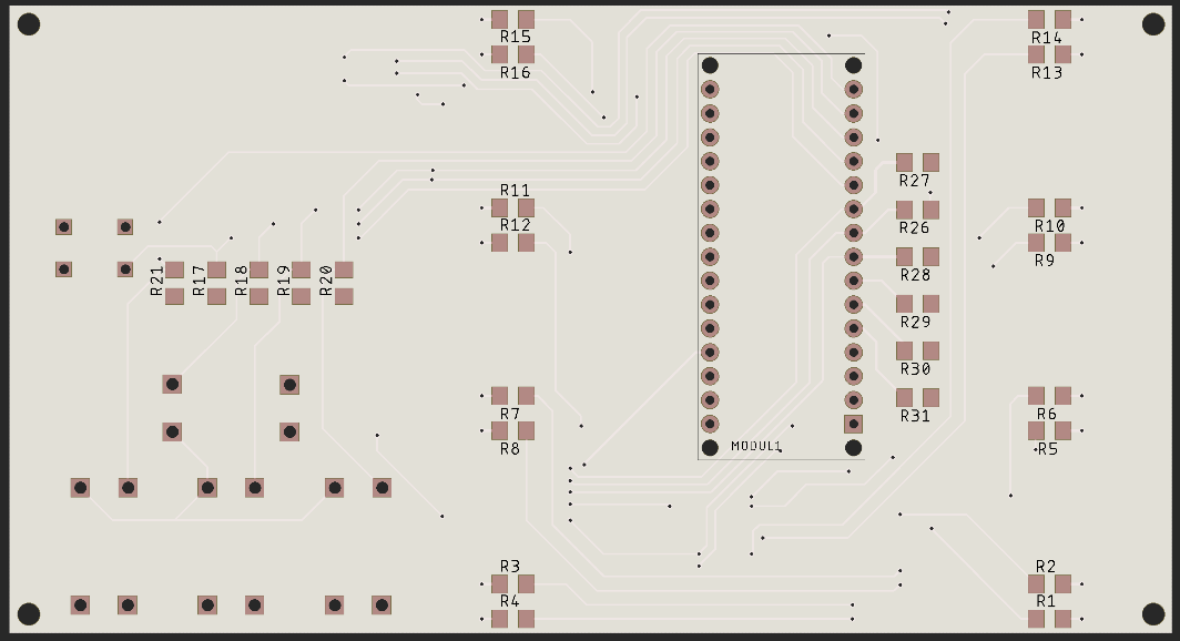
You have 4 LED row/column planes. We will connect these to the mainboard last. Start with the resistors. Note that there are two types of resistors. One resistor has the marking 181, the other has the marking 1002. The last digit corresponds with the magnitude (10^x). So 181 = 18 * 10^1 = 180Ω. 1002 = 100 * 10^2 = 10kΩ. The 180Ω resistors are for limiting the current to the LEDs. Therefore they are placed where the columns connect to the mainboard, on the backside of the board. The 180Ω resistors go on the pads with the markings R1 - R16. The rest of the pads (namely the ones by the arduino vias, pushbuttons, and the top side of the board) R17 - R31 are for the 10kΩ resistors.
Soldering SMD ICs
Once you have the resistors soldered in, try the MOSFETs or the shift registers. For the shift register, find the small circular indent on the corner of the chip which indicates pin 1, and line it up with the circular marking on the PCB footprint. Be careful not to solder it on backwards, since the chip is symmetrical. Don’t try the OR gate unless you are confident doing so, please come to me and let me help you if you don’t feel confident. You may damage the board or the component if you mess up. To solder SMD ICs, follow the same procedure as always. Start with the side with the least number of pins (if applicable). Using tweezers to hold the component, solder in a single pin. Reheat the joint and orient the chip such that it is sitting flat, and that the pins are straight. Make sure no pin is touching two pads. Once you are satisfied with the positioning, apply a generous amount of flux to the pins on the opposite side of the chip. Put a small amount of solder on the tip, and drag the tip across the pins/pads. The solder should flow on to every pin, and the flux should seperate any bridging. If some pins are bridged, this is okay. Apply more flux and drag the tip away from the chip between the two bridged pins to separate the bridge. If you used too much solder, you might need to use a desoldering pump/desoldering braid to remove the excess solder. Be careful when soldering SMD components as they are difficult to remove if you made a mistake after they are soldered in.
Soldering the remaining components
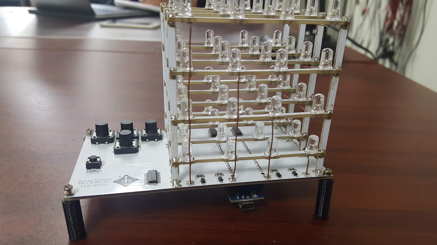
Now that all the resistors and ICs are soldered in, solder in the pushbuttons and Arduino. The Arduino goes on the backside of the board with the microUSB port on the side closest to the edge of the board.
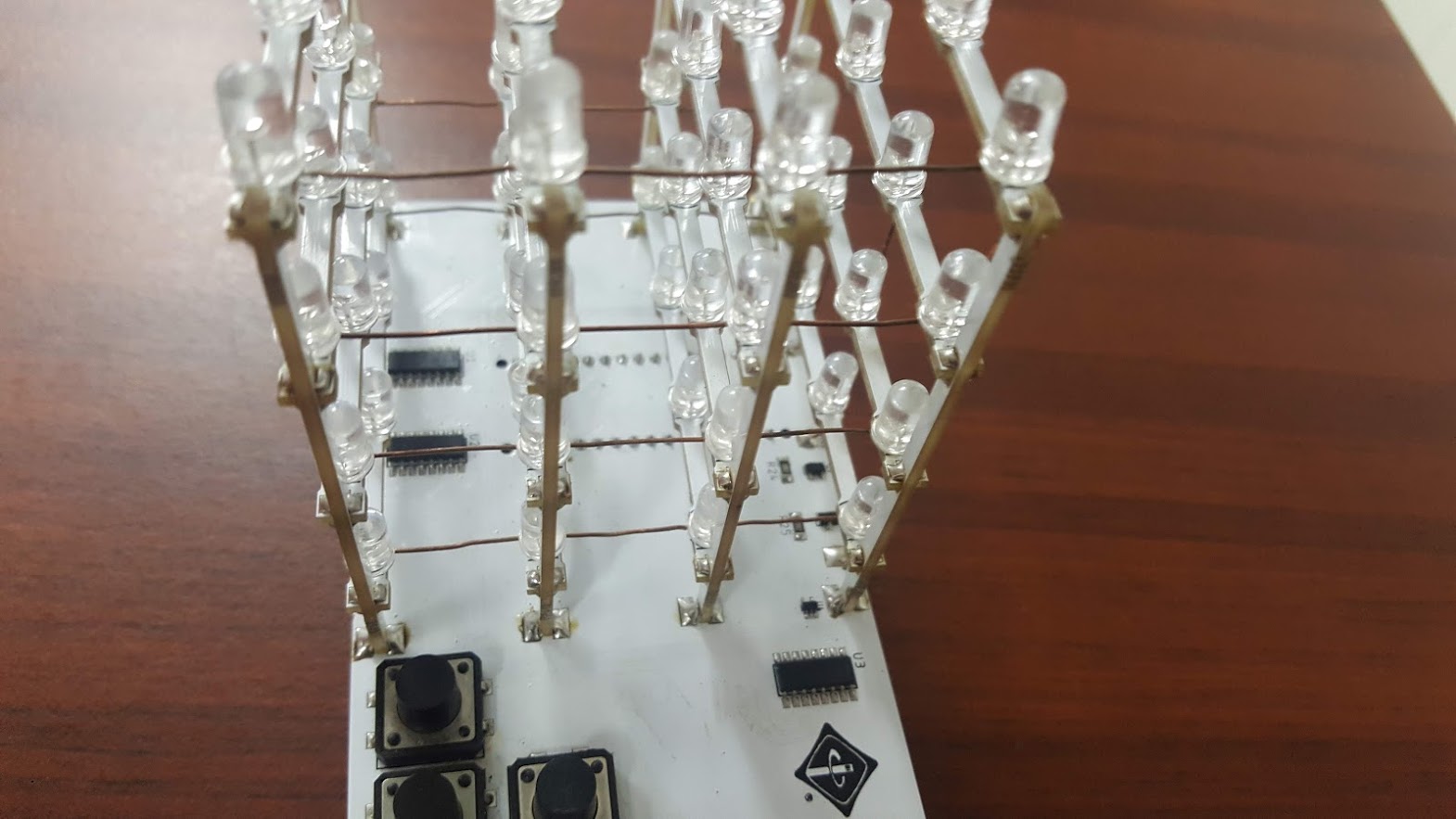
Soldering the cube assembly
Lastly we will solder the cube assembly. The black l between rows NEEDS TO BE ON THE LEFT SIDE (assuming the board is oriented such that you can read the logo). Solder in one joint, and reheat and move until the column is between the two pads and is perpendicular to the base. After all 4 planes are soldered in, you will need to connect the GND together for each layer. Cut a piece of solid core wire to the distance between the first and last plane. solder the wire to four LEDs in different rows on the same plane. Do this for each layer. Note that you are not connecting the layers together, only the rows in a single layer together (the GND is already connected in an individual row). Lastly, you will need to connect the layers to the mainboard. There are four pads at the edge of the mainboard by the MOSFETs. The silkscreen didn’t come out very good for the pads, so correspond the pad next to Q1 with layer 1, Q2 with layer 2, ect. Connect a piece of solid core wire from the negative terminal of one LED in layer 1 to the pad next to Q1. Do this for each layer.
Finishing thoughts
You should have everything to have the cube be functional now! Write a simple program using our Cube class. Test the following program. It should light up every LED on the cube. If an LED is not illuminated, check the soldering joints.
#include "Cube.h"

Cube c;

void setup()
{
  c.reset();
  for (int x = 0; x < 4; x++)
    for (int y = 0; y < 4; y++)
      for (int z = 0; z < 4; z++)
        c.bufferLED(x, y, z);
}

void loop()
{
  c.display();
}