Class 4
This class discusses the row and column assembly.
You should now have the following items:
- 1x row PCB panel (16 rows)
- 1x column PCB panel (8 columns)
- 64x green 5mm LED
Please read carefully before assembling the cube. There are a number of ways to make mistakes here that are very difficult to fix. Try to get it right the first try.
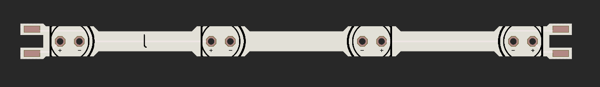
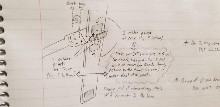
I recommend starting with the rows. 4 LEDs need to be soldered in per row. It is important to have the black silkscreen text facing upward when you are working with the row. Notice that there is a + and a - beside each plated hole on the board. The LONG leg of the LED goes in the + and the SHORT leg goes in the -. Notice that the + and - are mirrored about the middle of the board. The left side pattern is (+ -) (+ -) while the right side pattern is (- +) (- +). If you insert an LED backwards, it will not work. As a rule of thumb, the long leg of an LED should always be on the side closest to the edge of the row.
Once all the LEDs are soldered in, separate them from the panel. You will see a crease where the long piece of PCB connects all the rows together. Cut where the crease is using a pair of flush cutters. I recommend freeing about two rows then trimming the long piece of PCB so it is easier to access the next few rows. Be careful not to cut too far inward and damage the row PCB.
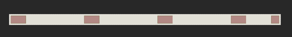
Now you should have 16 individual rows wih 64 LEDs soldered in, 4 per row. We now need to attach the row to the column. Notice the column has 4 rectangular shaped pads and one square shaped pad. The square shaped pad must be on the bottom. This square shaped pad is used to connect the row to the base PCB. The gap in each row is for a column to go in. I recommend starting with one column, soldering in the rows, then soldering in the second column. When soldering in the rows to the column you must have the black l marked between two LEDs on the LEFT side. If you have the black l alternating between rows, the wrong LEDs will light up when you use the software. This is also not an easy piece to disassemble and fix.
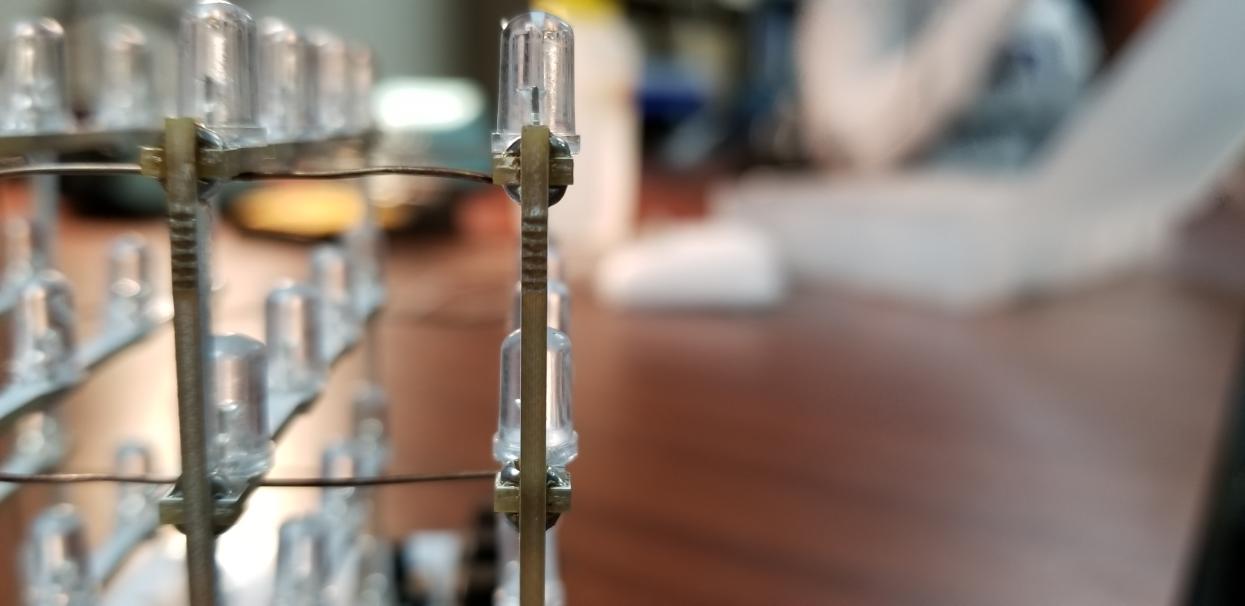
Each row should be centered between the rectangular pad on the column. There are 4 points that will need to be soldered for each row/column pair - two on each side of the column board, one above and one below the row. Solder just one of these solder points, then reheat the joint and adjust the row until it is perpendicular with the column. When you are satisfied with the positioning, solder the two points on the other side of the column, followed by the last point on the original side. If you solder the point on the original side first, it will melt the first point and you will lose your positioning since it is really just one pad. If your rows aren’t straight, the final result will both not look good and it will be difficult to solder it to the second column. See the below pictures for examples.
Your end result should be 4 planes of 2 columns and 4 rows each. Do not worry about attaching the planes together yet, we will do this when we have the base.