Class 3
This class discusses the firmware implementation for the cube.
Here is the source code for Cube class cpp file, which implements the functions defined in Cube.h
#include "Cube.h"

Cube::Cube()
{
  // Configure the necessary pins as output
  pinMode(SERIAL_IN, OUTPUT);
  pinMode(INPUT_CLK, OUTPUT);
  pinMode(LATCH_CLK, OUTPUT);
  pinMode(UPDATE_CLK, OUTPUT);
  pinMode(RESET, OUTPUT);
  pinMode(SET, OUTPUT);
}

void Cube::bufferLED(byte x, byte y, byte z)
{
  // Ensure the specified LED is within the bounds of the cube
  if (x > (size - 1) || y > (size - 1) || z > (size - 1)) return;

  // Convert the x,y position to a mapping of the format used for the buffer
  /*
   *  (0, 0) --> 000000000000001   -> 1
   *  (1, 0) --> 000000000000010   -> 2
   *  (2, 0) --> 000000000000100   -> 4
   *  ...
   *  (3, 3) --> 1000000000000000  -> 32768
  */
  unsigned short mapped = pow(2, (x + size*y)) + 0.5;

  // Add the LED to the buffer
  buffer[z] = buffer[z] | mapped;
}

void Cube::clearBuffer()
{
  for (byte i = 0; i < size; i++) buffer[i] = 0;
}

void Cube::reset()
{
  clearBuffer();
  // Remove any active LEDs
  display();
  // Clear the layer shift register
  digitalWrite(RESET, LOW);
  delayMicroseconds(period);
  digitalWrite(RESET, HIGH);
  delayMicroseconds(period);
  // Start the layer shift register
  digitalWrite(SET, HIGH);
  delayMicroseconds(period);
  digitalWrite(UPDATE_CLK, HIGH);
  delayMicroseconds(period);
  digitalWrite(UPDATE_CLK, LOW);
  delayMicroseconds(period); // probably not necessary
  digitalWrite(SET, LOW);
}

void Cube::display()
{
  // Update each layer (z-axis)
  for (byte i = 0; i < size; i++)
  {
    // Update x-y plane
    for (byte j = 0; j < size*size; j++)
    {
      // Retrieve the state of bit j on the current layer
      byte curr = (buffer[i] >> (size*size - 1 - j)) &  1;
      // Load in the bit
      digitalWrite(SERIAL_IN, curr);
      // Toggle the input clock to push the bit through
      digitalWrite(INPUT_CLK, HIGH);
      // Provide time for the input to update
      delayMicroseconds(period);
      // Toggle the input clock to wait for the next bit
      digitalWrite(INPUT_CLK, LOW);
      // Provide time to wait for the next bit
      delayMicroseconds(period);
    }
    // Toggle the latch clock to save the output
    digitalWrite(LATCH_CLK, HIGH);
    // Provide time for the output to latch
    delayMicroseconds(period);
    // Toggle the latch clock before loading new data
    digitalWrite(LATCH_CLK, LOW);
    // Provide time before changing the layer
    delayMicroseconds(period);
    // Toggle the update clock to switch to the next layer
    digitalWrite(UPDATE_CLK, HIGH);
    // Provide time to switch layers
    delayMicroseconds(period);
    // Toggle the update clock to work with the selected layer
    digitalWrite(UPDATE_CLK, LOW);
  }
}
Note that the function names are prefixed by Cube::. This indicates that the function belongs to the class Cube (we call these methods). Let’s go through each method one at a time.
void Cube::bufferLED(byte x, byte y, byte z)
This function takes an (x, y, z) coordinate and adds it to the current buffer.
if (x > (size - 1) || y > (size - 1) || z > (size - 1)) return;
First we check to make sure the given coordinate is valid. We check each coordinate to see if it is greater than 3, and exit the function if it is. The coordinates run from 0 to 3 (4 values), so each coordinate value must not exceed 3.
unsigned short mapped = pow(2, (x + size*y)) + 0.5;
Next we must convert our (x, y) coordinate to the appropriate LED ID that we use to describe which LED we want to be active. The LED ID scheme is shown below.
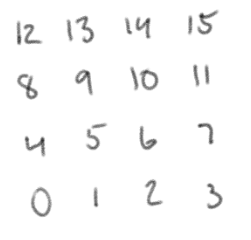
the function x + size*y performs this mapping. For example, coordinate (3, 3) => 3+ 4*3 = 15.
We perform the pow function (arguments are base, exponent) to achieve the result 2^(x + size*y). This gives a 1 bit for bit we want to change and 0 in every other bit. For example, given the coordinate (1, 2), this maps to 2^(1 + 4*2) = 2^9 = 512 = 1000000000 (in binary).
We add 0.5 to the result because pow returns a floating point number which often gives you a little less than the ideal number we want, which gets truncated down. Adding 0.5 forces a round up instead of round down.
buffer[z] = buffer[z] | mapped;
Remember that our buffer is an array of size 4. The z coordinate specifies what which layer we want to access, and thus which index of the array we should access. We take our mapped value and perform a bitwise or with the current value of the buffer for the specified layer. The bitwise or operation looks at two numbers bit by bit and performs a OR operation on each individual bit. Thus, a bitwise or will force the bit that we want to change to 1 to be set to 1, while leaving the remaining bits alone. This is because if the current bit in the buffer holds a 0, and we are asserting a 1, the output will be 1. If the current bit in the buffer holds a 1, and we are asserting a 1, the output is still 1. For example, assume we wish to enable the LED at (1, 2). This maps to 1000000000 in binary. Assume our buffer currently holds the configuration 1001010010110110. Performing a bitwise or..
1001010010110110 <- buffer
0000001000000000 <- mapped
1001011010110110 <- result
As you can see, the LED at position 6 was enabled. Note that the leftmost bit is LED 0 and the rightmost bit is LED 15. LED 6 was enabled without affecting the rest of the buffer.
The next method is
void Cube::clearBuffer()
This method empties the contents of the buffer and sets everything to 0.
for (byte i = 0; i < size; i++) buffer[i] = 0;
We use a simple for loop to set every value in the buffer to 0.
Next is
void Cube::display()
This method takes the contents of the buffer and displays it on the cube.
for (byte i = 0; i < size; i++)

  for (byte j = 0; j < size*size; j++)
We have a nested for loop. The first loop iterates through the layers of the cube, while the second loop iterates through each LED in a layer. As you can see, you must update every LED in each layer.
byte curr = (buffer[i] >> (size*size - 1 - j)) & 1;
Remember j starts at 0 and goes to 15. We are trying to find out if each LED should be on or off (0 or 1) so we need to check if bit j is a 0 or a 1. We do this by taking our current buffer, and performing the right shift function (»). This essentially removes the (size*size - 1 - j) rightmost bits. Note that size*size - 1 is equal to 15. So essentially we shift the buffer by 15 - j. For example, if our buffer currently contains 1001010010110110 and j = 6, we shift the buffer to the right by 15 - 6 = 9. So our buffer would contain 1001010. Next we perform the bitwise and operation with 1. This will check the whether the lowest bit of this new value is 1 or 0. Performing bitwise and…
1001010 <- modified buffer
0000001 <- 1
0000000 <- result
Thus, LED 6 should be set to 0.
digitalWrite(SERIAL_IN, curr);
digitalWrite(INPUT_CLK, HIGH);
delayMicroseconds(period);
digitalWrite(INPUT_CLK, LOW);
delayMicroseconds(period);
We input this value to the SERIAL_IN (input of the shift register) and trigger the input clock to shift it in. We provide a delay between triggering the clock to give it time to update.
digitalWrite(LATCH_CLK, HIGH);
delayMicroseconds(period);
digitalWrite(LATCH_CLK, LOW);
delayMicroseconds(period);
digitalWrite(UPDATE_CLK, HIGH);
delayMicroseconds(period);
digitalWrite(UPDATE_CLK, LOW);
After we load in the configuration for the specific layer, we must latch the output and switch to the next layer. To do this we trigger the latch clock to save the output of the shift register, then trigger the update clock to shift the layer shift register to the next layer. We then repeat this process for every layer.
Lastly is,
void Cube::reset()
This function resets the cube to a known state, which is necessary at the beginning of the program and whenever the player dies.
clearBuffer();
display();
First we clear the buffer and display the output. This essentially displays a buffer of all 0, which has the effect of turning off all currently active LEDs.
digitalWrite(RESET, LOW);
delayMicroseconds(period);
digitalWrite(RESET, HIGH);
delayMicroseconds(period);
Next we trigger the reset signal. Remember that reset for the shift register is active low. This will set the layer shift register to 0000.
digitalWrite(SET, HIGH);
delayMicroseconds(period);
digitalWrite(UPDATE_CLK, HIGH);
delayMicroseconds(period);
digitalWrite(UPDATE_CLK, LOW);
delayMicroseconds(period);
digitalWrite(SET, LOW);
Lastly turn on the set signal to load the initial 1 into the layer shift register. We trigger the update clock to shift the 1 in to the shift register.