Class 1
This class discusses the circuit design and implementation of the LED cube.
The LED cube uses an Arduino (or more generally, a microcontroller) to control its LEDs. The Arduino’s pins can output a 1 (5V) or a 0 (0V). These must be used to drive the LEDs. The first consideration should be, how will the Arduino interface with the cube’s LEDs? The intuitive solution is to connect a single LED in the cube to a single pin on the Arduino. This way, each LED will be addressable by the Arduino. However, we are limited in how many Arduino pins we have access to. For the Nano, we have around 15. This is clearly not suitable for a cube of size greater than 3. So we must do better.
We connect the positive terminal of each LED in one column (positive z-axis) together. In other words, the positive terminals of each LED in the positive z-axis are connected in parallel. Thus, applying a positive voltage on a single LED will apply that voltage to each LED above it. However, each LED’s negative terminal are kept separate. By applying a GND signal to a single LED’s negative terminal we can choose which LED has a complete circuit and can thus turn on.
By selecting which GND layer is connected to the main circuit’s GND, we can effectively select which LED becomes enabled. In this way, we can control all 64 LEDs with only 16 inputs, and a way to select the appropriate GND layer to enable. It must be noted that only one layer can be enabled at a time. If more than one layer is active, unwanted LEDs will be enabled due to the fact that all positive terminals are connected vertically. The process for enabling LEDs is as follows:
- Set the bottom layer as the active GND
- Enable the corresponding LEDs (using the 16 on the bottom layer)
- Display the LEDs
This process can be repeated for each layer. Remember that we only need to enable the corresponding LEDs on the bottom layer, because LED positive terminals are connected vertically. As long as the correct GND layer is active, the LEDs will display on the correct layer. This raises the question, how do I enable LEDs on two different layers at the same time? Well we can simply iterate through the layers, loading a new configuration for each layer, at a high enough frequency that all of the layers appear to be active simultaneously.
However, this still requires 16 pins plus a mechanism to control the active GND layer. We can still do better. A shift register is employed to manage this task. The shift register used for this project has 1 main input, and 8 main outputs. A shift register takes a series of binary numbers and shifts them through its outputs at every clock cycle. In other words, it takes a serial input and turns it in to a parallel output. In addition, we can connect the last output of one shift register to the input of a second shift register (effectively connecting them in series) to double the amount of bits it can hold. By doing so, we have a 16 bit shift register.
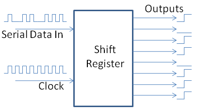
If we connect each output of our 16 bit shift register to one of the vertical columns on the bottom layer of the cube, we can control every LED using only one input pin, assuming we can toggle through the GND layers. For example, if we input 1000000000000001 into the shift register, this corresponds to enabling LED0 and LED15. The shift on the shift register happens at every clock cycle. So a clock is needed to keep the shifting happen on a fixed interval. One problem with this is that the LEDs will randomly change as the 16 bit number is being loaded in. However, the shift register has a function called latch. The latch essentially ‘saves’ the output. In other words, the value in the shift register will not reflect on the output until the latch is pulled high. So after the 16 bit number is loaded in, we pull the latch high. Then we set it low and load in the next 16 bit number. We can use a second clock, which runs at 16x the frequency of the input clock, for the latch function.
A third shift register is used to manage the layers. As stated before, only one GND layer can be active at a time, so we can create a pattern in the form 1000 -> 0100 -> 0010 -> 0001 (where 1 is the active GND layer). To implement this a single 1 must be inputted to the shift register to set the initial state. After this, the forth output can be connected to the shift register input to have the cycle repeat indefinitely. Because we cannot have our set function from the arduino and the forth output of the shift register both connected to the shift register input simultaneously, an OR gate is used with the Arduino’s set function as one input, the forth output as the second input, and the shift register input as the output. After the first 1 is set from the Arduino, the Arduino’s set output is set to 0. Thus the input of the shift register will be determined solely by the forth output of the shift register.
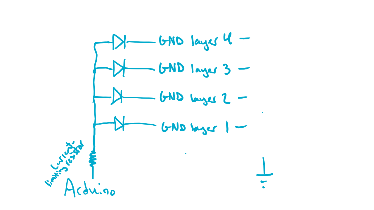
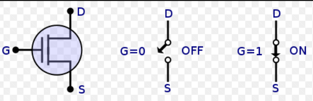
There is one more issue, and that is mapping the 1 output of the shift register to setting an active GND layer. To do this a transistor is used for each layer. A transistor works like a switch; it has three terminals: the drain, gate, and source. If the voltage on the gate is high, the drain connects to the source. If teh voltage on the gate is low, the drain is disconnected from the source. We can use the shift register outputs to the gates of the transistors, the GND layers to the drains, and the Arduino’s true GND to the source. This way when the shift register outputs a 1, it will connect the appropriate GND layer to the true GND.
This covers the circuit description. To reiterate, the display process works as follows.
- Set the GND layer with the GND layer shift register
- Load in a 16 bit configuration with the 16 bit shift register
- Latch the outputs of the shift registers
- Display the layer
- Go to the next layer and repeat
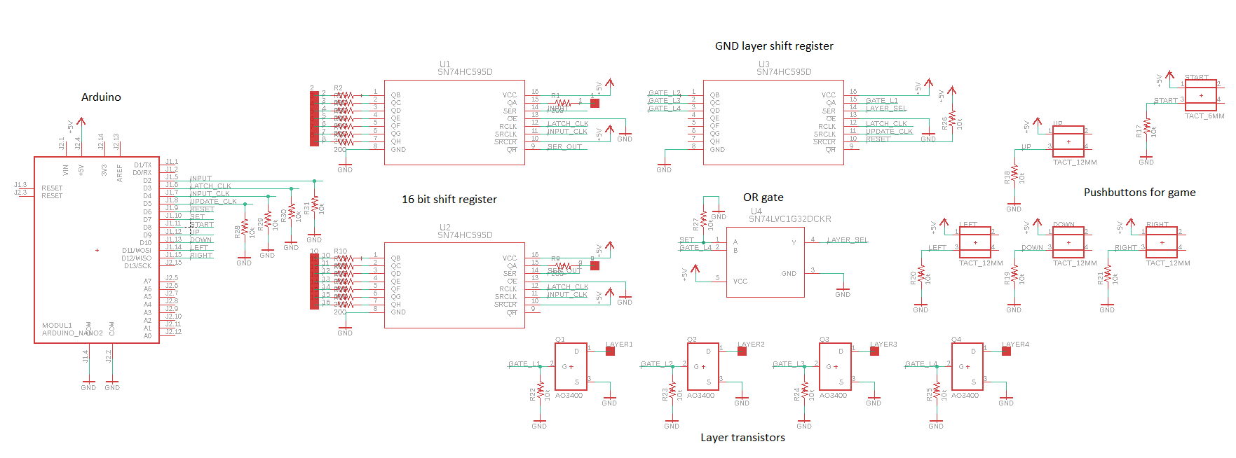
This process is happening very quickly, similar to a computer display refreshing. This gives the illusion that all LEDs can operate independently. Here is an overview of the circuit schematic with the components annotated.